
“It turns the dark and strange arts of shader programming into something understandable and non-evil”
Main
This is the node in which all your other nodes in the end link to. It has several inputs that all serve different purposes. The animated images below show all of the inputs and how they behave when changed over time. Most of them animate back and forth between 0 and 1 (Black and White)  Diffuse This is the main color of your shaders. The diffuse color will receive light, have light falloff depending on the light-normal angle, and be shaded by shadows.  Diffuse Power This is the exponent of the falloff of the light-normal angle. Can be used to get an extra metallic look when using values above 1. Note that this does not currently conserve energy, whenever that is enabled.  Specular This is the color of the specular highlights of your shader. Higher values are brighter, black will not affect the shader at all.  Gloss This is the exponent of the specular highlights. Higher values will make it look shiny, values approaching 0 will make it look matte. Note that if you have unchecked gloss remapping, you should avoid using gloss values below 1.  Normal This is the tangent-space normal direction, where you can connect normal maps or custom normal vectors.  Emission This is simply light that is always added to your shader, regardless of the lighting conditions.  Transmission This controls how much light is passed through when the light source is behind the surface currently being rendered. This can be useful for thin materials such as cloth or vegetation.  Light Wrapping This is a way of controlling the light-normal angle falloff offset, which can be used to get an effect similar to subsurface scattering. Works best for smooth objects. Inputting a red-ish value will make the red channel "wrap around" the object more than the others, making it look as if light passed into the mesh, and came out with a red wavelength, similar to how skin is shaded.  Diffuse Ambient Light This adds light to your shader, affected by your diffuse. Can be used with, for example, cubemap using the normal direction for image-based lighting (IBL), or ambient light  Specular Ambient Light This adds light to your shader, affected by your specular. Can be used with, for example, a cubemap using the view reflection direction for image-based lighting (IBL)  Diffuse Ambient Occlusion This dampens indirect diffuse light, such as light probes, indirect light, and diffuse ambient light  Specular Ambient Occlusion This dampens indirect specular light, such as reflection probes, and specular ambient light  Custom Lighting This input is active when your shader is set to unlit, allowing you to define custom lighting behaviour. The nodes you put here are per-light.  Opacity Opacity controls the transparency of the final pixel. Note that partial transparency is generally finicky to get right, especially when using deferred rendering.  Opacity Clip Opacity Clip is a way of controlling if the current pixel/fragment should draw or not. Always use Opacity Clip for objects that need transparency, but not partial transparency, as Opacity Clip is easily sorted, which Opacity is not.  Refraction Refraction is a screen-space UV offset for refracting the background pixels. Make sure you set the alpha to something below 1 before using, so that the refraction effect is visible.  Outline Width This will add an outline to your shader, rendered as an offset mesh with reversed face normals. Note that hard edges will break the outline.  Outline Color This controls the color of the outline.  Vertex Offset This can be used to animate shaders over time, or change the shape of the object in various conditions. You simply insert a XYZ coordinate for how much each vertex should be offset.  DX11 Displacement This works very much in the same way as Vertex Offset, but is used in conjunction with DX11 tessellation. (Note that DirectX is Windows only, requires a DX11 GPU and has to be enabled in Unity)  DX11 Tessellation This controls how many subdivisions you want to split your triangles into. (Note that DirectX is Windows only, requires a DX11 GPU and has to be enabled in Unity) |
Add
A + LMB
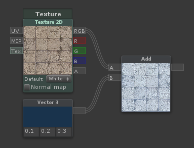 | Outputs the sum [A] + [B] |
Subtract
S + LMB
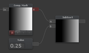 | Outputs the difference [A] - [B] |
Multiply
M + LMB
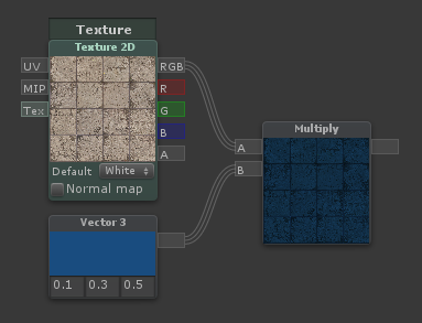 | Outputs the product [A] * [B] |
Divide
D + LMB
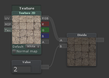 | Outputs the quotient [A] / [B] |
Reciprocal
Outputs the quotient 1 / input |
Power
E + LMB
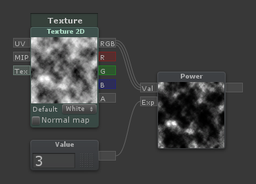 | Outputs the power [Val] ^ [Exp] |
Sqrt
Outputs the square root of its input |
Log
Outputs the logarithm of its input. You can switch log base in the dropdown menu |
Min
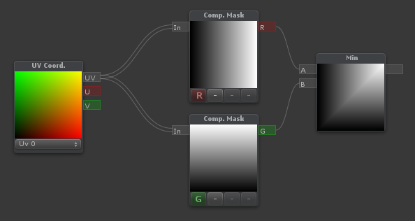 | Outputs the minimum of [A] and [B] |
Max
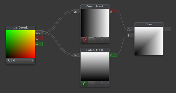 | Outputs the maximum of [A] and [B] |
Abs
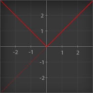 | Outputs the absolute value of its input. Essentially; it makes negative values positive |
Sign
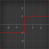 | Outputs the sign of its input. Values greater than 0 outputs 1 Values equal to 0 outputs 0 Values less than 0 outputs -1 |
Ceil
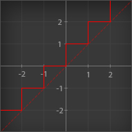 | Outputs its input rounded up to the nearest integer |
Round
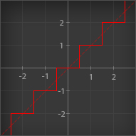 | Outputs its input rounded to the nearest integer |
Floor
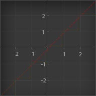 | Outputs its input rounded down to the nearest integer |
Trunc
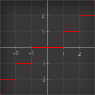 | Outputs its input rounded to the nearest integer towards zero. Essentially; it removes the decimals, leaving an integer |
Step (A <= B)
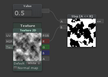 | Outputs 1 if [A] is less than or equal to [B], otherwise outputs 0 |
Smoothstep
Blends smoothly between two values, based on where a third value is in that range, outputting values between 0 and 1. Think of it as a clamped inverse lerp with a smoothed output value. |
If
I + LMB
Outputs the [A>B] input when [A] is greater than [B] Outputs the [A=B] input when [A] is equal to [B] Outputs the [A<B] input when [A] is less than [B] |
Frac
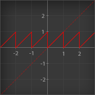 | Outputs the fractional part of its input. Essentially; it removes the integer part and keeps only the decimal part. An input of 4.32 would output 0.32. This node is particularly useful in conjunction with the Time node, which gives you a sawtooth wave over time |
Fmod
Outputs the remainder of [A] divided by [B] |
Clamp
Outputs its main input value, no less than [Min] and no more than [Max] |
Clamp (Simple)
The same as Clamp, but with two numerical inputs for Min and Max instead of node connectors |
Clamp 0-1
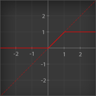 | Outputs its input value, no less than 0 and no more than 1 |
Lerp
L + LMB
 | Lerp is used to blend between two values or colors. If [T] is 0, it will output [A] If [T] is 0.5, it will output a halfway blend between [A] and [B] If [T] is 1, it will output [B] If [T] is any other value, it will output a linear blend of the two. |
Lerp (Simple)
The same as Lerp, but with two numerical inputs for [A] and [B] instead of node connectors |
InverseLerp
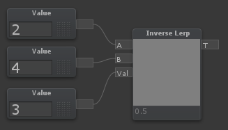 | InverseLerp is usually used to remap ranges. If [T] is equal to [A], it will output 0 If [T] is halfway between [A] and [B], it will output 0.5 If [T] is equal to [B], it will output 1 If [T] is any other value, it will output a linear blend of the two. |
Posterize
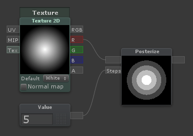 | Rounds values based on the value coming through [Steps]. A [Steps] value of 5 will create 5 bands in the 0 to 1 range |
Blend
B + LMB
 | Blends A over B using the specified method |
Remap
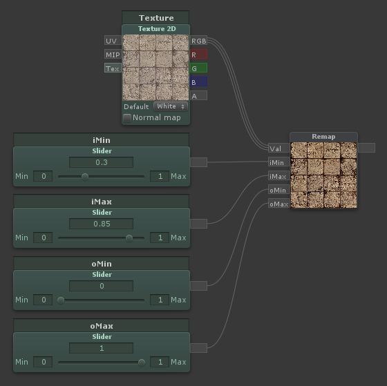 | Remaps a value from one range to another. Same as Remap (Simple), but with inputs instead of numerical constants |
Remap (Simple)
R + LMB
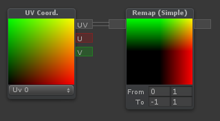 | Remaps a value from one range to another. For instance, if the node expects values from -1 to 1, but you want it to output a value from 2 to 5, you can type -1 and 1 on the first line, 2 and 5 on the second line |
Noise
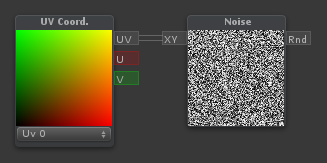 | Generates pseudorandom numbers based on a two-component input (Such as UV coordinates) |
One Minus
O + LMB
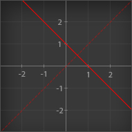 | Outputs 1 minus its input. When used with color inputs, it will invert the color |
Negate
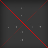 | Outputs the main input multiplied by -1. Essentially makes positive values negative, and negative values positive |
Exp
When Exp is selected: Outputs e to the power of its input When Exp 2 is selected: Outputs 2 to the power of its input |
Hue
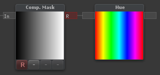 | Outputs an RGB color given a Hue |
HSV to RGB
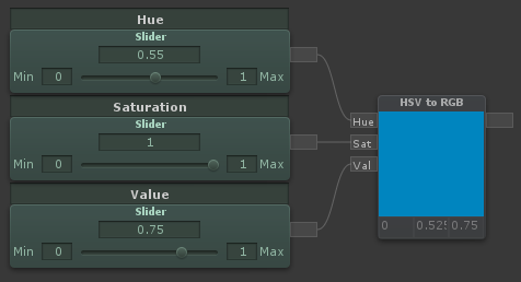 | Outputs an RGB color given a HSV (Hue, Saturation and Value) input. Hue and Saturation are between 0 and 1. Value is too, but can go beyond 1 to overexpose colors |
RGB to HSV
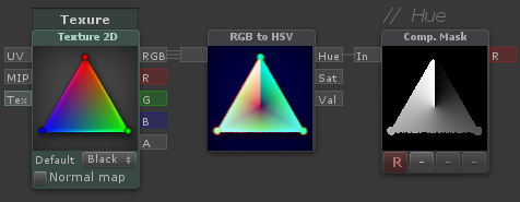 | Outputs HSV (Hue, Saturation and Value) components given a color input. Hue and Saturation are between 0 and 1. Value can go beyond 1 for overexposed colors |
Value
1 + LMB
A numerical value, can also be called a "Vector 1". A property version is also available. Values can be used with the Append node to create Vectors with more components. Values can also be multiplied with vectors/colors. For example, a vector (3,1,0) multiplied by a value of 0.5, outputs the vector (1.5,0.5,0) |
Vector 2
2 + LMB
A vector with two components/values. Usually used with UV coordinates. Adding a Vector 2 to UV coordinates, will translate the UVs. Multiplying UV coordinates with a Vector 2 will scale the UVs |
Vector 3
3 + LMB
A vector with three components/values. Usually used as a color, position or direction |
Vector 4
4 + LMB
A vector with four components/values. Usually used as a color with an alpha channel, or as a position with some extra data in the fourth channel. There are two parameters to expose in the inspector available. Color and Vector 4 parameter |
Texture 2D
T + LMB
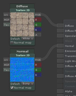 | Contains a reference to a texture and will sample a texture at a specific UV coordinate with a specific MIP level (if connected). If the [Tex] input is connected by a Texture Asset node, this will no longer be a parameter in the inspector. Outputs [RGB] as well as separate channels |
Texture Asset
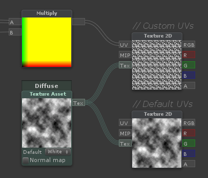 | Contains a reference to a texture. This is used to sample a single texture multiple times - Can only be connected to the [Tex] input of Texture 2D nodes. This will also be reflected in the inspector of the material, so the user only need to assign one texture |
Value (Property)
A numerical value; same as Value, but exposed in the material inspector |
Vector 4 (Property)
A vector with four components/values, same as Vector 4, but exposed in the material inspector as 4 separate X, Y, Z and W values |
Color
A vector with four components/values, same as Vector 4, but exposed in the material inspector with a color picker |
Cubemap
Contains a reference to a cubemap and will sample a it in a specific direction with a specific MIP level (If connected). Outputs [RGB] as well as separate channels |
Slider
Allows you to easily tweak a value between a min and a max value. Is also exposed to the inspector |
Switch
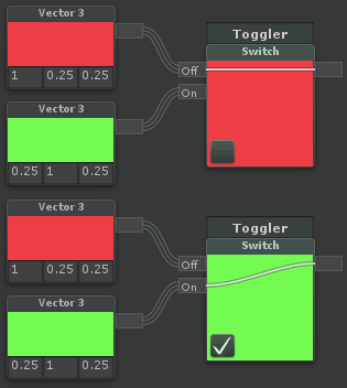 | Switches between two inputs based on a checkbox. Note that this cannot be used to optimize a shader, it will process both branches, but only show one |
Toggle
A value that is either 0 or 1 based on a checkbox |
Dot Product
Outputs the Dot product between [A] and [B]. Essentially; for two normalized vectors, it outputs how far they point away from each other. If they point in the same direction, it outputs 1, if they are perpendicular to each other, it outputs 0, if they point in opposite directions, it outputs -1. Dropdown selections: Standard - Regular Dot Product Positive - Makes all negative values 0 Negative - Makes all positive values 0 Abs - Makes all negative values positive Normalized - Outputs in the range 0 to 1 instead of -1 to 1 The graph below show how the different modes behave when using two normalized vectors. On the X axis you have the angle between them, on the Y axis you have the output value:  |
Cross Product
Outputs the Cross product of [A] and [B]. Essentially; it outputs a vector perpendicular to both input vectors |
Reflect
Outputs the reflection vector of an incoming vector [I] as if reflected/bounced on a surface with the normal [N] |
Normalize
N + LMB
Outputs the normalized version of the input vector. Essentially; sets the length of the vector to 1, while keeping the same direction |
Append
Q + LMB
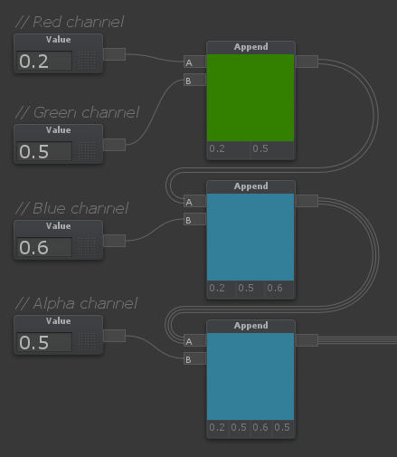 | Outputs a single vector from multiple input values/vectors. For example, if [A] is a Vector 2, and [B] is a Value (Vector 1), the node will output a Vector 3, where [A] is in the red and green channel, while [B] is in the blue channel |
Component Mask
C + LMB
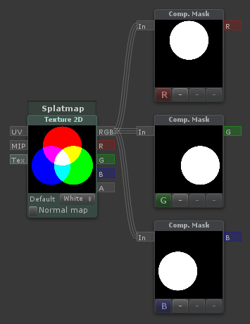 | The component mask can be used to reorder or extract channels of a vector |
Desaturate
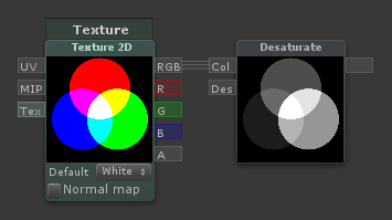 | Outputs a desaturated version of the input [Col]. [Des] Determines how desaturated it is. A value of 1 means fully desaturated, 0.5 means half-desaturated, 0 means no desaturation |
Channel Blend
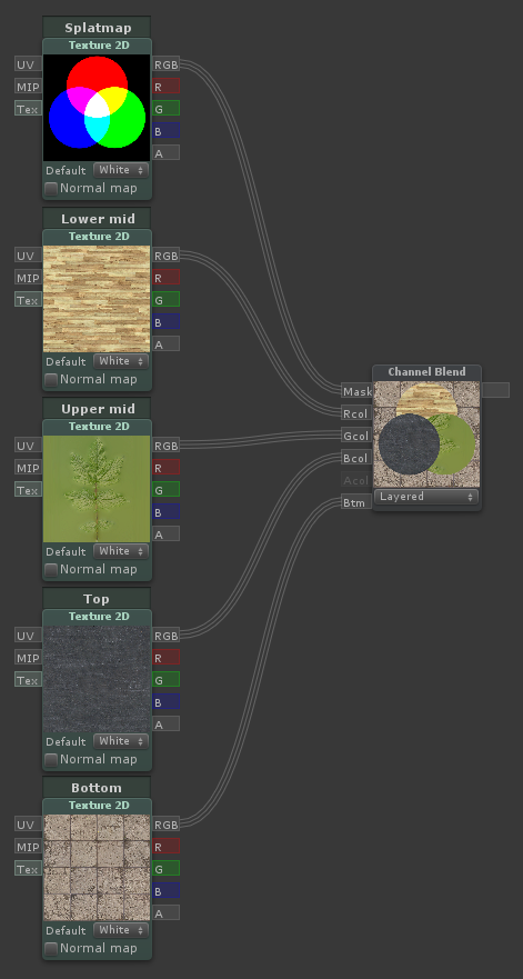 | Outputs the sum of each component of the mask multiplied by the corresponding color input. Useful for triplanar blending |
Normal Blend
Combines two normal directions, where the base normal is perturbed by the detail normal |
Distance
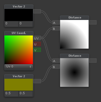 | Outputs the distance between the two input points [A] and [B] |
Length